How to Draw M Ei Diagram
7.5: Deflection by Moment-Area Method
- Page ID
- 42975
The moment-expanse method uses the surface area of moment divided by the flexural rigidity (\(M / E D\)) diagram of a axle to determine the deflection and gradient along the beam. In that location are two theorems used in this method, which are derived below.
First Moment-Area Theorem
To derive the first moment-area theorem, consider a portion \(AB\) of an elastic curve of the deflected axle shown in Figure vii.8b. The beam has a radius of curvature \(R\). Figure vii.8c represents the angle moment of this portion. According to geometry, the length of the arc \(ds\), of the radius \(R\), subtending an angle \(d \theta\), is equal to the product of the radius of curvature and the angle subtend. Therefore,
\[d s=R d \theta\]
Rearranging equation ane suggests the post-obit:
\[\frac{d \theta}{d s}=\frac{1}{R}\]
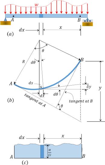
\(Fig. vii.8\). Deflected beam.
Substituting equation 7.14 into equation seven.8 suggests the post-obit:
\[d \theta=\frac{Thou}{E I} d southward\]
Since \(ds\) is infinitesimal because of the small-scale lateral deflection of the beam that is allowed in engineering, it tin exist replaced by its horizontal projection \(dx\). Thus,
\[d \theta=\frac{Yard}{E I} d ten\]
The bending \(\theta\) between the tangents at \(A\) and \(B\) can thus be obtained past summing up the subtended angles past the infinitesimal length lying between these points. Thus,
\[\begin{array}{l}
\int_{A}^{B} d \theta=\int_{A}^{B} \frac{M}{E I} d x \\
\operatorname{Or} \theta_{B / A}=\theta_{B}-\theta_{A}=\int_{A}^{B} \frac{G}{E I} d x
\finish{assortment}\]
Equation vii.17 is referred to equally the first moment-expanse theorem. The beginning moment-surface area theorem states that the total modify in slope between \(A\) and \(B\) is equal to the area of the bending moment diagram between these two points divided by the flexural rigidity \(EI\).
Second Moment-Expanse Theorem
Referring over again to Figure 7.eight, it is required to determine the tangential difference of betoken \(B\) with respect to point \(A\), which is the vertical distance of point \(B\) from the tangent drawn to the elastic bend at point \(A\). To practise so, first calculate the contribution \(\delta \Delta\) of the element of length \(dL\) to the vertical distance. According to geometry,
\[\delta y=x d \theta\]
Substituting \(d \theta\) from equation vii.15 to equation 7.xviii suggests the following:
\[\delta y=\frac{Yard x}{E I} d ten\]
Hence,
\[y=\int_{A}^{B} \frac{Thou x}{E I} d ten\]
Equation 7.twenty is referred to equally the 2d moment area theorem. The 2d moment-area theorem states that the vertical distance of bespeak \(B\) on an elastic bend from the tangent to the curve at point \(A\) is equal to the moment with respect to the vertical through \(B\) of the expanse of the angle moment diagram between \(A\) and \(B\), divided past the flexural rigidity, \(EI\).
Sign Conventions
The sign conventions for moment-area theorems are every bit follows:
(1)The tangential deviation of a point \(B\), with respect to a tangent fatigued at the elastic curve at a indicate \(A\), is positive if \(B\) lies above the drawn tangent at \(A\) and negative if it lies below the tangent (run across Figure vii.9).
(two)The slope at a signal \(B\), with respect to a tangent fatigued at a point \(A\) in an rubberband curve, is positive if the tangent drawn at \(B\) rotates in a counterclockwise direction with respect to the tangent at \(A\) and negative if it rotates in a clockwise management (meet Figure vii.9).
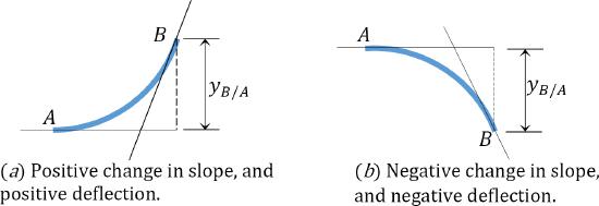
\(Fig. 7.ix\). Sign convention representation.
Process for Analysis by Moment-Area Method
•Sketch the free-body diagram of the beam.
•Draw the \(Grand/EI\) diagram of the beam. This will look like the conventional bending moment diagram of the beam if the beam is prismatic (i.eastward. of the aforementioned cantankerous section for its unabridged length).
•To determine the slope at whatever point, find the angle between a tangent passing the indicate and a tangent passing through another point on the deflected curve, carve up the \(Thou/EI\) diagram into simple geometric shapes, and so apply the get-go moment-area theorem. To make up one's mind the deflection or a tangential deviation of whatsoever point forth the beam, utilise the second moment-surface area theorem.
•In cases where the configuration of the \(Chiliad/EI\) diagram is such that it cannot be divided into elementary shapes with known areas and centroids, it is preferable to draw the \(M/EI\) diagram past parts. This entails introducing a fixed support at whatever convenient point along the beam and cartoon the \(M/EI\) diagram for each of the practical loads, including the support reactions, prior to the application of any of the theorems to determine what is required.
Table 7.one. Areas and centroids of geometric shapes.
| Geometric Shape | Area | Centroid | ||
| Ci | Cii | |||
| Rectangle | 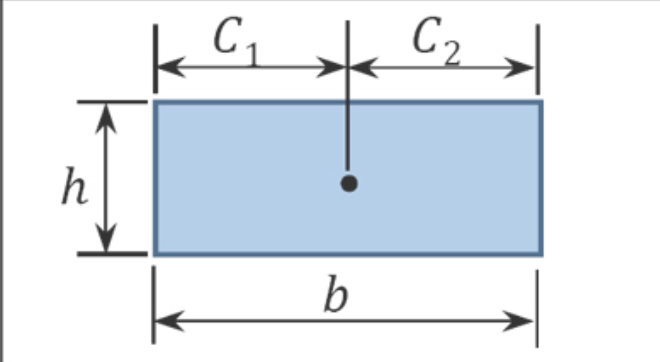 | \(bh\) | \(\frac{b}{2}\) | \(\frac{b}{2}\) |
| Triangle | 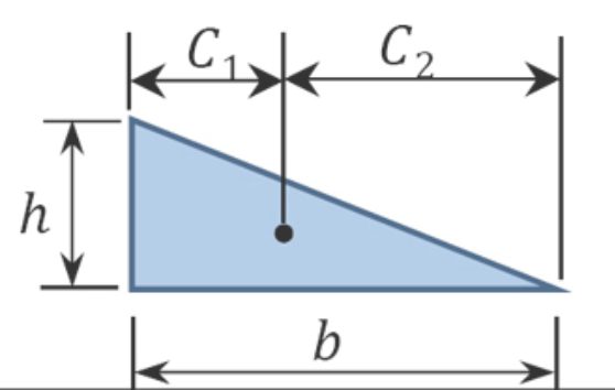 | \(\frac{bh}{ii}\) | \(\frac{b}{3}\) | \(\frac{2b}{three}\) |
| Parabolic Spandrel | 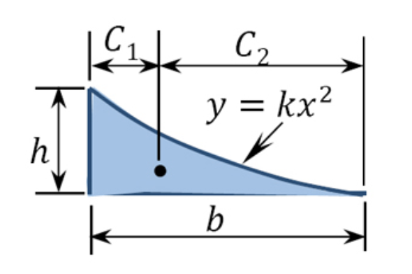 | \(\frac{bh}{three}\) | \(\frac{b}{4}\) | \(\frac{3b}{iv}\) |
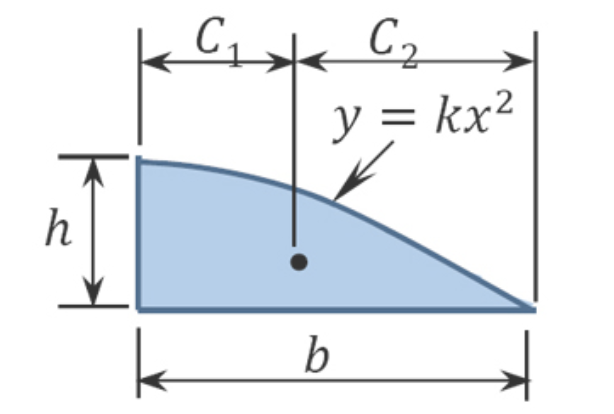 | \(\frac{2bh}{3}\) | \(\frac{3b}{8}\) | \(\frac{5b}{8}\) | |
| Cubic Spandrel | 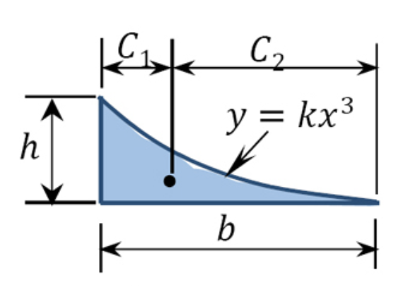 | \(\frac{bh}{4}\) | \(\frac{b}{five}\) | \(\frac{4b}{5}\) |
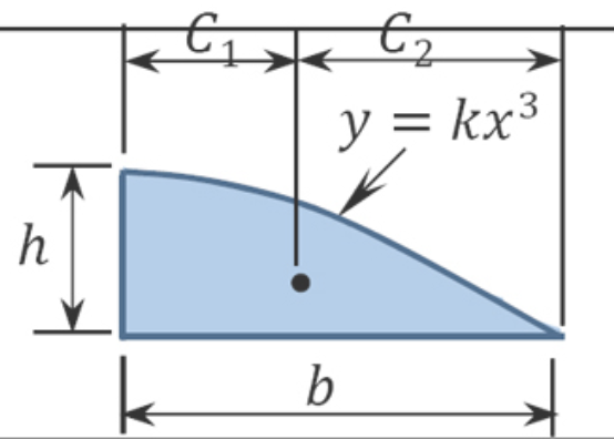 | \(\frac{3bh}{4}\) | \(\frac{2b}{5}\) | \(\frac{3b}{5}\) | |
| Full general Spandrel | 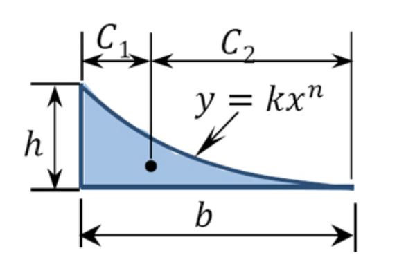 | \(\frac{bh}{n+one}\) | \(\frac{b}{north+ii}\) | \(\frac{b(n+ane)}{n+2}\) |
Instance 7.vii
A cantilever beam shown in Effigy seven.10a is subjected to a concentrated moment at its free end. Using the moment-area method, determine the gradient at the free end of the axle and the deflection at the complimentary terminate of the axle. \(EI\) = abiding.
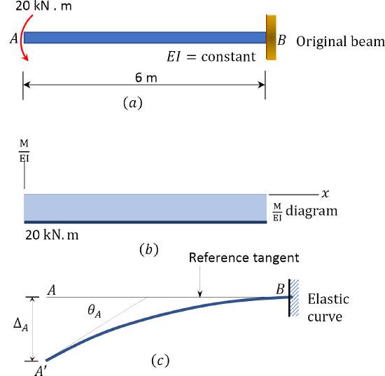
\(Fig. 7.ten\). Cantilever beam.
Solution
(\(M/EI\)) diagram. First, depict the bending moment diagram for the axle and divide it by the flexural rigidity, \(EI\), to obtain the \(\frac{Grand}{Due east I}\) diagram shown in Effigy vii.10b.
Slope at \(A\). The slope at the free end is equal to the area of the \(\frac{M}{East I}\) diagram between \(A\) and \(B\), co-ordinate to the first moment-surface area theorem. Using this theorem and referring to the \(\frac{M}{E I}\) diagram suggests the following:
\(\theta_{A}=-\left(\frac{ane}{E I}\right)(six)(20)=-\frac{120}{E I}\)

Deflection at \(A\). The deflection at the free end of the axle is equal to the moment with respect to the vertical through \(A\) of the area of the \(\frac{Thousand}{E I}\) diagram between \(A\) and \(B\), according to the 2nd moment-surface area theorem. Using this theorem and referring to Effigy 7.10b and Effigy 7.10c suggests the following:
\(\Delta_{A}=-\left(\frac{one}{Due east I}\correct)(6)(twenty)(three)=-\frac{360}{E I} \quad \Delta_{A}=\frac{360}{East I} \downarrow\)
Example 7.8
A propped cantilever beam carries a uniformly distributed load of 4 kips/ft over its unabridged length, as shown in Figure vii.11a. Using the moment-surface area method, determine the gradient at \(A\) and the deflection at \(A\).
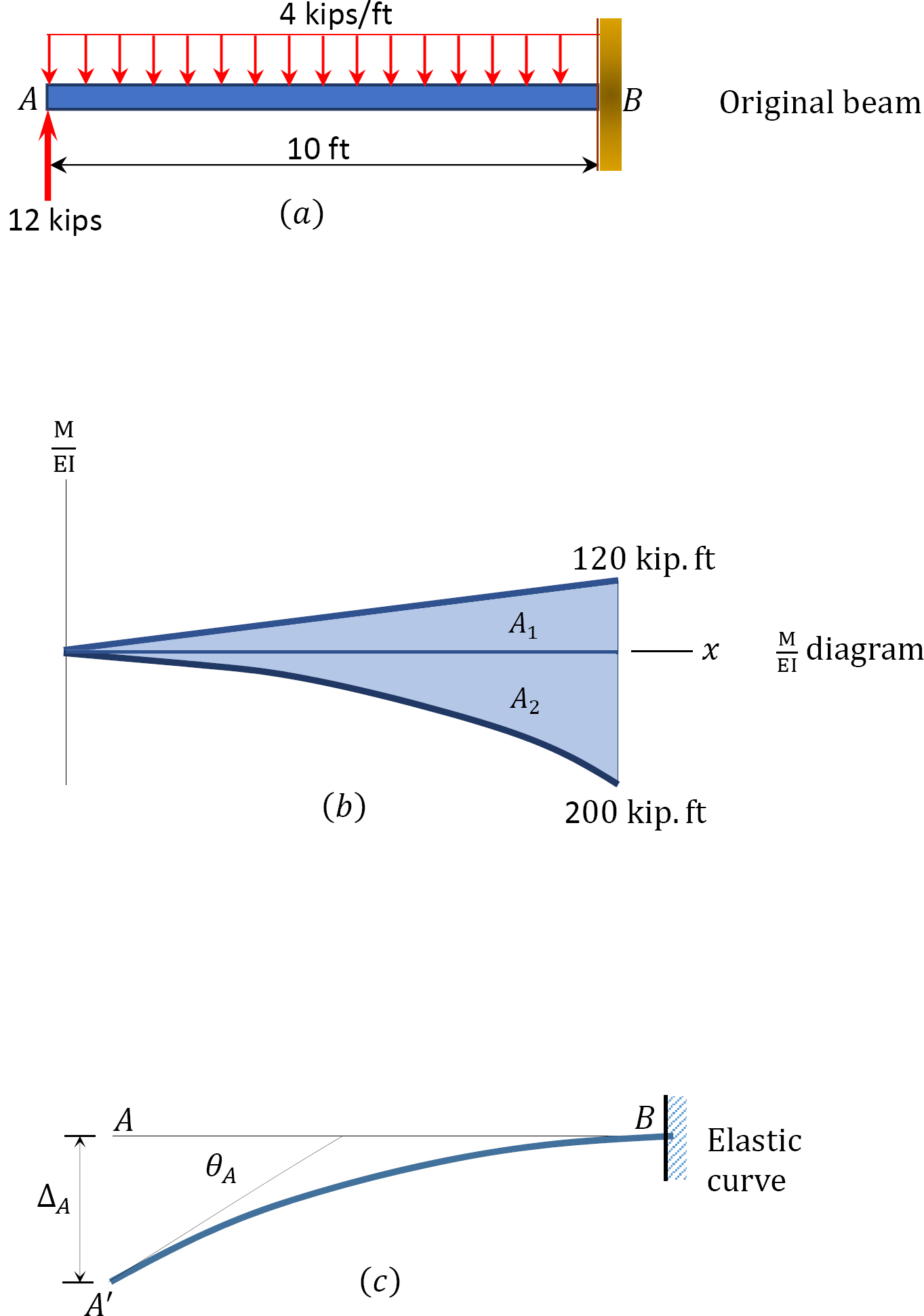
\(Fig. 7.11\). Propped cantilever beam.
Solution
(\(M/EI\)) diagram. First, describe the angle moment diagram for the beam and split up it by the flexural rigidity, \(EI\), to obtain the \(\frac{M}{E I}\) diagram shown in Figure vii.11b.
Slope at \(A\). The gradient at the gratuitous end is equal to the area of the \(\frac{M}{Due east I}\) diagram between \(A\) and \(B\). The expanse between these two points is indicated as \(A_{1}\) and \(A_{2}\) in Figure 7.11b. Employ Table seven.one to find the computation of \(A_{2}\), whose arc is parabolic, and the location of its centroid. Noting from the table that \(A=\frac{1}{3} b h\) and applying the kickoff moment-area theorem suggests the following:
\(\theta_{A}=A_{i}-A_{2}=\left(\frac{1}{Due east I}\right)\left(\frac{1}{2}\right)(10)(120)-\left(\frac{ane}{Eastward I}\right)\left(\frac{10 \times 200}{iii}\correct)=-\frac{66.67}{E I}\)
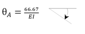
Deflection at \(A\). The deflection at \(A\) is equal to the moment of expanse of the \(\frac{Chiliad}{Eastward I}\) diagram betwixt \(A\) and \(B\) near \(A\). Thus, using the second moment-area theorem and referring to Figure 7.11b and Figure vii.11c suggests the following:
\(\Delta_{A}=A_{1}\left(\frac{L}{3}\right)-A_{2}\left(\frac{3 L}{4}\right)=\left(\frac{1}{East I}\right)\left(\frac{i}{two}\correct)(ten)(120)\left(\frac{2 \times 10}{iii}\correct)-\left(\frac{i}{E I}\right)\left(\frac{ten \times 200}{3}\right)\left(\frac{3 \times 10}{four}\right)=-\frac{1000}{Due east I} \quad \Delta_{A}=\frac{1000}{East I} \downarrow\)
Example seven.9
A just supported timber axle with a length of 8 ft will behave a distributed floor load of 500 lb/ft over its unabridged length, as shown Figure vii.12a. Using the moment area theorem, determine the slope at terminate \(B\) and the maximum deflection.
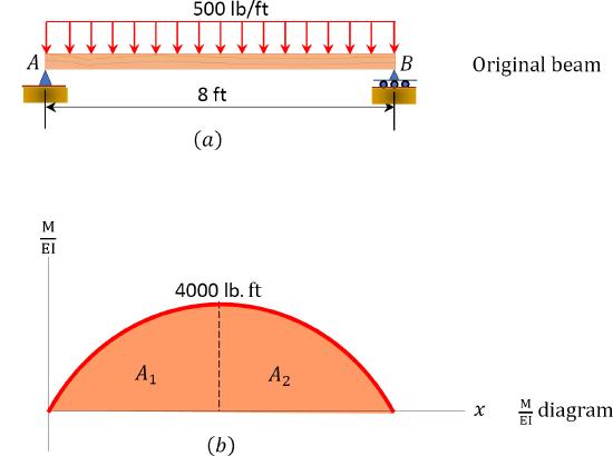

\(Fig. 7.12\). Merely supported timber beam.
Solution
(\(K/EI\)) diagram. Showtime, draw the angle moment diagram for the beam, and divide information technology past the flexural rigidity, \(EI\), to obtain the \(\frac{Thousand}{E I}\) diagram shown in Effigy seven.12b.
Slope at \(B\). The gradient at \(B\) is equal to the area of the \(\frac{K}{Eastward I}\) diagram between \(B\) and \(C\). The area between these 2 points is indicated equally \(A_{2}\) in Figure 7.12b. Applying the first moment-area theorem suggests the following:
\(\theta_{B}=A_{2}=\left(\frac{1}{E I}\right)\left(\frac{two b h}{3}\right)=\left(\frac{1}{E I}\correct)\left(\frac{2(4)(4000)}{3}\right)=\frac{10666.67}{Eastward I}\)

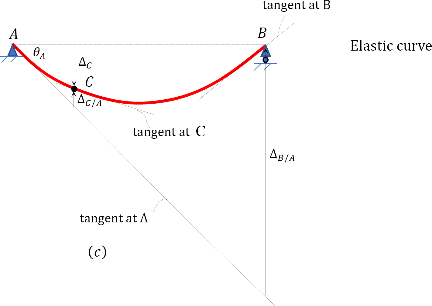
Maximum deflection. The maximum deflection occurs at the center of the beam (indicate C). It is equal to the moment of the area of the \(\frac{K}{E I}\) diagram betwixt \(B\) and \(C\) virtually \(B\). Thus,
\(\Delta_{c}=A_{2}\left(\frac{five b}{8}\right)=\left(\frac{1}{E I}\correct)\left(\frac{2(4)(4000)}{3}\correct)\left(\frac{5(4)}{8}\right)=\frac{26666.67}{East I}\)

Case seven.10
A prismatic timber axle is subjected to two full-bodied loads of equal magnitude, every bit shown in Effigy seven.13a. Using the moment-area method, determine the slope at \(A\) and the deflection at point \(C\).

\(Fig. vii.xiii\). Prismatic timber axle.
Solution
(\(M/EI\)) diagram. Get-go, draw the angle moment diagram for the beam and divide it by the flexural rigidity, \(EI\), to obtain the \(\frac{Thousand}{East I}\) diagram shown in Figure 7.13b.
Slope at \(A\). The deflection and the rotation of the beam are pocket-sized since they occur within the elastic limit. Thus, the gradient at back up \(A\) tin be computed using the small-scale angle theorem, every bit follows:
\(\theta_{A}=\frac{\Delta_{B / A}}{50}=\frac{\Delta_{B / A}}{half-dozen}\)
To determine the tangential deviation of \(B\) from \(A\), employ the second moment-area theorem. According to the theorem, information technology is equal to the moment of the area of the \(\frac{M}{Eastward I}\) diagram between \(A\) and \(B\) about \(B\). Thus,
\(\begin{assortment}{l}
\Delta_{B / A}=A_{1}\left(1.5+iii+\frac{1}{three} \times 1.five\right)+A_{2}(1.five+1.5)+A_{iii}\left(\frac{two}{3} \times one.5\right) \\
\Delta_{B / A}=\frac{one}{E I}\left[\frac{1}{2}(1.5)(half-dozen)\left(\frac{2}{3} \times 1.5\correct)+(iii)(6)(ane.5+1.five)+\frac{1}{2}(1.5)(half dozen)\left(1.5+3+\frac{one}{3} \times 1.5\right)\correct] \\
\Delta_{B / A}=\frac{81}{E I}
\end{array}\)
Thus, the slope at \(A\) is
\(\theta_{A}=\frac{\Delta_{B / A}}{50}=\frac{81}{6 East I}=\frac{thirteen.v}{E I} \quad \theta_{A}=\frac{13.v}{E I}\)
Deflection at \(C\). The deflection at \(C\) can exist obtained by proportion.
\(\begin{array}{50}
\frac{\Delta_{B / A}}{half dozen}=\frac{\Delta_{c}+\Delta_{C / A}}{one.v} \\
\Delta_{c}=\frac{(1.5)\left(\Delta_{B / A}\right)}{six}-\Delta_{C / A}
\stop{array}\)
Similarly, the tangential divergence of \(C\) from \(A\) can exist determined as the moment of the area of the \(\frac{One thousand}{Due east I}\) diagram between \(A\) and \(C\) nearly \(C\).
\(\Delta_{C / A}=\frac{1}{Eastward I}\left[\frac{one}{2}(1.5)(vi)\left(\frac{2}{3} \times 1.5\correct)\correct]=\frac{nine}{two E I}\)
Therefore, the deflection at \(C\) is
\(\Delta_{c}=\frac{(1.5)(81)}{6 East I}-\frac{9}{two E I}=\frac{15.75}{Due east I} \quad \Delta_{c}=\frac{15.75}{Due east I}\)
Source: https://eng.libretexts.org/Bookshelves/Mechanical_Engineering/Introduction_to_Aerospace_Structures_and_Materials_%28Alderliesten%29/02:_Analysis_of_Statically_Determinate_Structures/07:_Deflection_of_Beams-_Geometric_Methods/7.05:_Deflection_by_Moment-Area_Method

0 Response to "How to Draw M Ei Diagram"
Post a Comment